['electroncircuits.blogspot.com'];

Cell Phone RF Radiation Detector LED

From rookieelectronics: This is my favorite project, its too simple and very interesting because it does not require any voltage source. it converts RF frequency waves from cell phone (whenever you call or send a text) to little current to flash a LED.

Cell Phone RF Radiation Detector
Actually this project is also called as LED power meter, it is used to test RF equipments. It can detect output power of our FM transmitters, by simply connecting voltmeter in the place of the load(LED) of this circuit.

A Low-Voltage Cut-Off Switch

A Micro controller-based voltage cutoff circuit, currently in use on several motorcycles. It is designed to monitor the voltage level for the battery, and activate an accessory circuit when the level is sufficiently high. If the level drops below a calibrated level, the accessories are cut off. [Link]


Low-Voltage Cutoff Switch

One million Raspberry Pi PCs Sold Since February Launch

The Raspberry Pi, a credit card-sized computer designed for tinkerers, has sold an impressive one million units since it's launch last year, the foundation detailed this weekend.


One million Raspberry Pi PCs Sold Since February Launch

Developed in the UK by the Raspberry Pi Foundation, and launched in late-February at RS Components and Premier Farnell computer shops, the Raspberry Pi went quickly, selling out within minutes. Priced at under £22, the tiny computer has proved a fun project for household hacks and small computing tasks.

One million Raspberry Pi PCs Sold Since February Launch

The ARM-based PC features a HMDI socket, a video output, two USB ports, Ethernet, audio output, and SD card slot. Power is provided either by a battery or a standard mobile phone charger.

The PC's focus on getting people programming looks to be well on its way to being accomplished, according to the numbers just released. The cute infographic below details that all of the Raspberry Pis sold weigh the same as 200,000 iPhone 5s, and stacked end to end would be taller than 111 Empire State Buildings.

Start Your Car Using Your Cell Phone

This is the same technique used to launch fireworks with your cell phone. Instead of turning on the vibrate motor when someone calls, your car will start instead.A The phone can be kept charged by hooking it up to the cigarette lighter of your car (you can do this from behind the dashboard if you want it to be discreet).A You can also set alarms via your phone’s calendar. [Link]


Start Your Car Using Your Cell Phone

Gnomio Smart Watch for Windows Phone

The Gnomio is an innovative wrist watch designed for Windows Phone 8 smartphones. As we can see from the images, the smart watch comes in two models, both the model feature minimalistic and stylish design, while the black model also features an anodized aluminum watch case for premium look.


Gnomio Smart Watch for Windows Phone

Moreover, each digital watch runs on Windows Embedded Compact 7 operating system, using built-in Bluetooth technology, the wrist watch is able to connect with your Windows Phone 8 smartphone, and notifying you through soft vibration about incoming calls, emails and messages, moreover, the smart watch can also access to Windows Phone Store for more apps.

Apart from that, other specs of the smart watch also include ARM 270MHz processor, 64MB DDR2 RAM, 8GB flash memory, a capacitive touchscreen display with 240 x 240 pixels resolution, 3-axis gyro, accelerometer, ambient light sensor, 3.5mm audio jack, built-in rechargeable battery and etc.

Gnomio Smart Watch for Windows Phone


At present, the inventor of Gnomio is raising fund at Indiegogo. Pledging $81 will let you own the smart watch for Windows phone. If you’re interested, jump to Indigogo official site for more details.

Make A Cheap USB Powered Fan

Find out how to make a cheap yet quite efficient fan from parts purchased at the dollar store. This fan can be made for about $2 (plus tax). It would be even better if you can get a double ended USB wire, in which case you could make 2 USB fans for $3 (plus tax). That definitely beats the $15 or $20 stores tend to charge for the same kind of devices.[Link]


Glowing LED Desk Alerts you of Emails, IMs

KEA desks are DIY-er favorites. Take this IKEA Gallant desk for instance. The desk comes with a frosted class top, and where there’s frosted glass, cool LED effects are not far behind.  The desk monitors HTTP requests and illuminates LEDs when a new chat or email message arrives.

Glowing LED Desk Alerts you of Emails, IMs

Each light is individually addressable so plenty of illuminated patterns are possible.8 LED modules are connected via a USB controller to the desktop. 

Glowing LED Desk Alerts you of Emails, IMs
 A node.js web server listens for incoming HTTP requests and connects to Growl ( a program which manages social  notifications).  The instructions detail the process of implementing the various hardware and software components of this project.[Link]

Glowing LED Desk Alerts you oF Emails, IMs

USB Peripheral to Google’s Nexus One Android Phone

A Nexus One Android phone normally won’t let you run any other peripheral device. But if you hack the phone to run on “USB Host mode” you can plug in all sorts of USB peripherals. USB Host mode lets you to external hard drives, digital cameras, external monitors, etc. to your Android phone just like a regular computer!

USB Peripheral to Google’s Nexus One Android Phone

The Android hack shows how to enable USB Host mode by tinkering the Android firmware.With the USB Host mode enabled, a Nexus one can be used like a standalone workstation. As the video above shows, you can play movies, start a webcam, connect a keyboard, and even a large monitor display. If you give it a try, let us know how it goes in the comments. [Link]

How to Power Your USB Gadgets with Bike


Power USB Gadgets With Your Bike
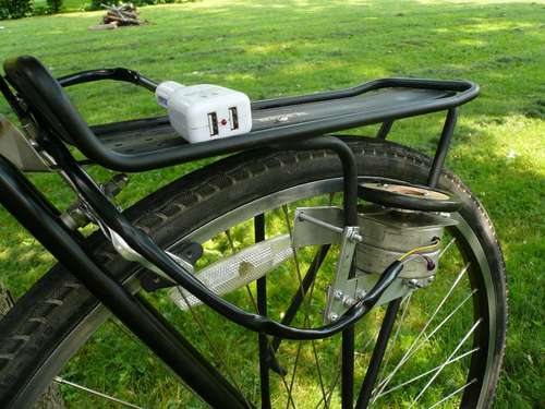
With more and more gadgets coming out every day that utilize USB for charging, it’s almost necessary to have a USB port available at all times.  This DIYer decided to create a 5V generator using his bike and a modified USB car charger. The 5V USB plugs are situated under his seat and he has a carrying rack for cellphones, GPS, or MP3 players on the go.
Power USB Gadgets With Your Bike
The USB bike generator works by placing a rotating wheel perpendicular to the rear wheel of the bike with a heavy spring. The mini-wheel turns a stepper motor to generate a charge that is then smoothed out by an in-line rectifier.[Link]

Solar Powered Lithium Ion Battery Charger

The circuit below feeds a controlled current and voltage to a 3.6v lithium ion battery. The current is limited to 300ma and the voltage is limited to 4.2 volts. The circuit uses a LTC1734 IC from Linear Technology. No diode is needed between the circuit and a 6 volt solar panel. Some very nice 6 volt solar panels are available from www.plastecs.com Their SP6-200-12 cranks out about 1 watt while the SP6-300-12 can produce about 2 watts. Assuming a 6 hour sunlit day, the 2 watt panel will pump about 1.8 amp-hours into a battery.


Circuit Project: Circuit Solar Powered Lithium Ion Battery Charger

TDA2030A Amplifier used in Home Theaters

TDA2030A is a well used class AB audio amplifier IC. This one is mostly used in nowadays home theater systems for it’s some good features,
  1. Small size IC(package PENTAWATT V, almost size of regular TO220)
  2. Maximum voltage range (upto 44Volts Vs MAx)
  3. Very low harmonic and cross-over distortion.
  4. Suited for more reliable applications without regulated supply
  5. Up to 35Watts RMS driver output
  6. Thermal shutdown protection
This IC require less external components too, making it easier for a beginner to make this on veroboard. The original circuit I got from it’s datasheet. A little modified circuit below,
TDA2030A Amplifier used in Home Theaters
This can be operated with single supply line, but that topology gives less output power, hence this bi-voltage topology is used everywhere. We need to provide +/- 12V to it. We can easily get +12V and -12V from a 12-0-12 CT step down transformer. And, as this IC doesn’t require regulated supply, we can feed voltage directly from rectifier with just a capacitor.
Well, the IC costs around 25 rupees, and together with all other materials as PCB, other parts the cost of final board doesn’t exceed 70-75 rupees.
                                                                                                                  Source:circuitsprojects.net

Touch Sensitive Light Dimmer

With IC SLB0586A from Siemens you can build a simple touch light dimmer circuit that will allow you to adjust the lamp intensity. Together with a TIC206D triac, it enables smooth regulation of light intensity from a bulb of 10W – 400W. A coil of 100µH/5A is required to suppress switching noise.The voltage supply is obtained through R2, C2, D1 and C3 and is about 5.3V below the network potential. The touch sensor that is used to drive the IC is connected at pin 5 through two 4.7M? resistors, R5 and R6, in order to ensure user security.
In the adjustable touch lamp schematic we can see three selection connection , for selecting one of three modes of the IC. When the B connection is used, the light will always be ON at the last level that we used. With A or C connection the light will be ON at the minimum intensity. With B or C, the purpose of regulation is reversed with each use.
Schematic of the adjustable light with touch sensor
Circuit Project: Touch light dimmer circuit
When the sensor is touched for a short period of time (50 – 400 ms), the lamp will be ON or OFF. If the sensor is touched for a longer period of time it will start the regulation process. Warning! This touch light dimmer circuit has some points where lethal 220V is present, please do not try this project if you are not qualified.
Source: electroschematics.com

Model Railway Time

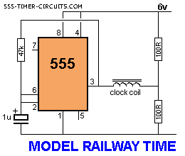
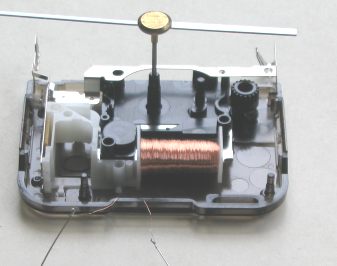
Here is a circuit that will convert any clock mechanism into Model Railway Time. For those who enjoy model railways, the ultimate is to have a fast clock to match the scale of the layout. This circuit will appear to “make time fly” by turning the seconds hand once every 6 seconds.
The timing can be adjusted by changing the 47k. The electronics in the clock is disconnected from the coil and the circuit drives the coil directly. The circuit takes a lot more current than the original clock (1,000 times more) but this is one way to do the job without a sophisticated chip.
Circuit Project: MODEL RAILWAY TIME Circuit

Classroom Microphone

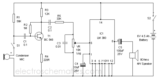
This Audio Amplifier circuit is useful in classrooms to reduce the strain of lecturing ,if the surrounding environment is noisy. It uses the power amplifier IC LM 380 that gives 2 watts output which is sufficient in a confined area. The Amplifier is portable and the whole circuit and the battery can be enclosed in the Speaker box itself.
Circuit Project: Classroom Microphone Circuit
The circuit uses a preamplifier stage around NPN transistor BC 548 and a power amplifier around LM380.An external Collar MIC can be given to the input using an audio jack .The voice signals are amplified by T1 and fed to IC1 input through the volume control VR. Capacitor C3 reduce the undesirable howling from the speaker.
LM380 is the general purpose audio amplifier and its gain is internally fixed at 34 dB. Its output is short circuit proof with internal thermal limiting. The IC works between 5 to 22 volts DC and is dual in line version.
Classroom Microphone Circuit diagram
Circuit Project: Classroom Microphone Circuit
Assemble the circuit on a common PCB. A 9 volt PP3 battery can be used to make the unit compact. If the amplifier is used for many hours, a 6 Volt 4.5 Ah rechargeable battery is a nice choice. If it is used, a charger input facility should be provided .Use a small good quality 8 Ohms speaker. If the output is not sufficient, use a high power amplifier IC circuit in the place of LM 380.

LM 380 Pin connection    

3V Headphone Amplifier


Many new devices require a headphone connection, but due to the high level of integration and miniaturization there is usually little room left. The low supply voltage and/or battery voltage also causes problems. If no special techniques are used, the output power and headroom are severely limited. The MAX4410 made by Maxim over-comes these problems not just by virtue of its small size, but also by including an internal supply inverter (charge-pump). This requires only two small external ceramic SMD capacitors (C6 and C7).

The supply voltage to the output stage is now symmetrical and the outputs are therefore relative to ground (no DC offset). This gets round the need for large output capacitors to stop a DC voltage from reaching the headphones. A DC-coupled output can also be implemented using two bridge amplifiers, but virtually all plugs for stereo headphones are asymmetric and use 3-pole connectors (common ground), which can’t be connected to a bridge output.

Each channel can be individually turned off (SHDNL and SHDNR) by jumpers JP1 and JP2. During normal operation these two inputs should be connected to the positive supply. When both channels are turned off the charge pump is also switched off and the current consumption drops to about 6µA.

3V headphone Amplifier circuit diagram
The IC also has thermal and short-circuit protection built in. The IC switches to standby mode when the supply voltage is too low and it has a circuit that prevents power-on and off plops at the outputs. The recommended supply voltage is between 1.8 V and 3.6 V. The IC can deliver about 80mW per channel into a 16Ω load. The power supply should be able to output at least 200mA. In practice this means that when you use a power supply that also powers other circuits, it should have at least 300mA in reserve.

The amplifiers are configured in inverting mode with a gain set by the ratio of two resistors (R3/R1 or R4/R2); the input impedance is determined by R1 and R2. C1 and C2 are required to decouple any possible DC-offset from the inputs. In the MAX4410 evaluation kit these are small tantalum capacitors, but we don’t recommend these for use in audio applications. Plastic film types would be much better, although they take up much more room.

HF decoupling is provided by 100 pF capacitors connected in parallel with R3 and R4. These set the bandwidth of the amplifiers to just over 150 kHz. The typical distortion is 0.003%. For more details you should refer to the MAX4410 datasheet. It is also worth looking at the datasheet for the associated evaluation kit.

The choice of capacitors for decoupling etc., their positioning on the board and the overall layout are very critical and demand a lot of attention. Furthermore, the 14-pin TSSOP package (with a pin spacing of 0.65 mm) and SMDs in 0402 packages make it very difficult to construct this circuit yourself. The IC is also available in a (much more difficult to solder) UCSP 16 package (ball grid array, only 2.02 by 2.02 mm).

Phone Lines Used for Setting Up Whole House Speaker System

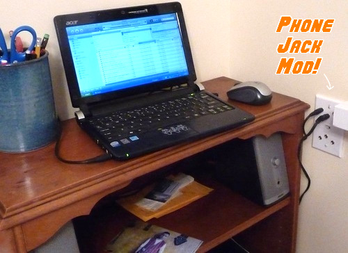
The project illustrates the use of pre-existing telephone wiring system in order to run a house-wide and low cost audio system, as seen in the image below. It would be expensive to use podcasts or Internet radio for streaming audio around the house. For a 3-level house, this would permit the same audio to be played throughout although the sensibilities of audiophiles may be violated since the ON/OFF and volume controls are on the remote speakers.

Hacks and Mods: Phone Lines Used for Setting Up Whole House Speaker System

Pictured in the image below is the master jack that contains an extra port that will be used for input. This is responsible for feeding the audio into the network after taking from the laptop. The 3.5mm headphone jacks are accommodated by all the rest which are stationed around the house. This implies that any big stereos or iPod earphones that is preferred can be plugged in.

Hacks and Mods: Phone Lines Used for Setting Up Whole House Speaker System

The power to run the stereos is the coolest thing about this hack wherein it can be supplied using the Cat 3 telephone cable, which contains 8 strands, through the network. This will work only if the lines have 3 extra wires and no land line is in use. The wiring in the a wall junction box is shown in the picture below which illustrates how simple it was constructed using basic circuitry and soldering required. For each stereo running from each socket, this will save having two wires.

Hacks and Mods: Phone Lines Used for Setting Up Whole House Speaker System

Another image shows a cover panel for an in-wall junction box which shows both speaker jacks and a phone jack while using Cat 3 wire. the 4 screws at the bottom can connect to a 2-line phone via the Cat 3 phone jack in the cent and the 3 screws at the top are for the audio jacks. To secure the wood to the box, a double-side tape will work well.

Hacks and Mods: Phone Lines Used for Setting Up Whole House Speaker System

Solar Powered Lithium Ion Battery Charger

The circuit below feeds a controlled current and voltage to a 3.6v lithium ion battery. The current is limited to 300ma and the voltage is limited to 4.2 volts. The circuit uses a LTC1734 IC from Linear Technology. No diode is needed between the circuit and a 6 volt solar panel. Some very nice 6 volt solar panels are available from www.plastecs.com Their SP6-200-12 cranks out about 1 watt while the SP6-300-12 can produce about 2 watts. Assuming a 6 hour sunlit day, the 2 watt panel will pump about 1.8 amp-hours into a battery.


Circuit Project: Circuit Solar Powered Lithium Ion Battery Charger

A Simple Hard Drive Switch


Readers of this blog who have both a PC and children face a particular problem. Since the young tend not to be too circumspect in their surfing habits, parents’ files are in permanent danger of being infected with viruses or deleted. There is also the risk of children or their friends gaining unauthorized access to files not intended for their eyes.

Perhaps a separate PC for the children would take up too much space or is ruled out for pedagogical reasons; in that case, the solution is to install two separate hard drives in the PC, one for the children and one for the adults. Ideally the two hard drives will each carry their own operating system and have their own software installed. As long as things are arranged so that the children can only boot their own drive, the parents’ data will remain secure.

All that is required, besides a second drive, is a specially-designed hard drive switch. This can be achieved, as has already been described in this blog Electronics, by switching the two drives between master and slave modes using the IDE cable, and only activating the master drive in the BIOS. However, the IT skills of children should not be underestimated: the BIOS is easily changed back. The solution described here is a bit more secure.

Both drives are bootable and configured as masters. One is connected to IDE bus 1, and the other to IDE bus 2. The power supply voltages (+12 V and +5 V) are, however, only applied to one drive at a time. In principle, a simple double-pole changeover switch would do the job, but that has the disadvantage that it is possible to forget to reset the switch to child mode after use, especially if the switch is hidden.

Circuit Project: Hard Drive Switch circuit diagram
A better solution is to have to press a (hidden) button during boot to put the machine into parent mode. We will now see how this is done. If the button is not pressed when the PC is switched on, then, after a short delay of about 0.7 s (determined by R1, C1, D2 and the base-emitter junction threshold voltage of the Darlington pair formed by T1 and T2) RE2 pulls in. RE1 remains un-energized and hence the children’s drive connected to K2 is active.

Subsequently pressing S1 has no effect since RE1 has been isolated by the contacts of RE2. If the secret button is pressed, either briefly or continuously, during the 0.7 s sensitive period after the computer is switched on, RE1 pulls in immediately and holds itself in this state. D3 now prevents RE2 being subsequently activated. Since the contacts of RE1 have changed over, the PC now boots from the parents’ drive.

It is impossible to forget to return the computer to child mode, since the computer will always start up in this mode if the secret button is not pressed. A 12 V miniature relay with contacts rated for 100mA is suitable for RE2. The contacts of RE1 should be rated for the currents taken by a typical hard disk drive (say 2 A to 3 A). A key switch can be used instead of a secret button as a last resort against resourceful children, since the circuit will continue to operate correctly if S1 is left in parent mode permanently while the computer is on.

DIY LED Camera

The process mentioned below shows how we can convert the LEDs to the light sensors so that it can be used for many other purposes also. Read on to know more about this.As the Blinkenlight Shield has 20 of them, 20 pixel camera can be developed by it. After performing the experiment, it is recommended to reset the jumper setting to default. LED or Light Emitting diodes usually act as the photo diodes and are optimized to produce the light.
Hacks and Mods: DIY LED Camera
LEDs can be used to make the light detectors that can be helpful in various conditions. The idea behind this is to reverse bias the diodes by turning the IO pins to output low so that the LEDs used will act as capacitors and will not be conducted. The current produced due to the LED is very small, and the photo current produced discharges the LED capacitors. After charging, the IO pins have to be switched to high Z so as to generate the light. The light produced and the current are directly proportional to each other.

After the discharging of capacitors, the pin will move towards high from low. By measuring the time taken for discharge, the amount of light reached by the LED can be calculated. After processing all the LEDs, they can be used in a serial line but it should be taken care of that this is done in a separate step to avoid any mistake in measuring the discharge time.

Portable Solar Lantern

This portable solar lantern circuit uses 6 volt/5 watt solar panels are now widely available. With the help of such a photo-voltaic panel we can construct an economical, simple but efficient and truly portable solar lantern unit. Next important component required is a high power (1watt) white LED module.

When solar panel is well exposed to sunlight, about 9 volt dc available from the panel can be used to recharge a 4.8 volt /600 mAh rated Ni-Cd batterypack. Here red LED (D2) functions as a charging process indicator with the help of resistor R1. Resistor R2 regulates the charging current flow to near 150mA.

Solar Lantern Circuit Schematic
Circuit Project: Portable Solar Lantern

Assuming a 4-5 hour sunlit day, the solar panel (150mA current set by the charge controller resistor R2) will pump about 600 – 750 mAh into the battery pack. When power switch S1 is turned on, dc supply from the Ni-Cd battery pack is extended to the white LED (D3). Resistor R3 determines the LED current. Capacitor C1 works as a buffer.

Note: After construction, slightly change the values of R1,R2 and R3 up/down by trial&error method, if necessary.